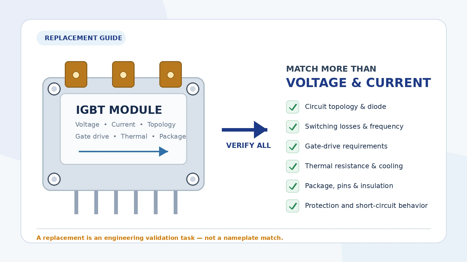
Replacing an IGBT module is not as simple as finding another part with the same voltage and current printed on the data sheet. Two modules may both be described as 1200 V, 200 A devices and still be unsuitable substitutes because their internal circuit, switching behavior, gate-drive requirements, thermal path, terminal arrangement or protection characteristics are different.
A reliable replacement process therefore begins with the original module and the operating conditions of the equipment. The objective is not merely to find a module that can turn on, but to find one that can operate safely within the existing inverter, motor drive, UPS, welding machine, servo system or industrial power converter.
Important: IGBT modules are used in equipment containing hazardous voltages and stored energy. Replacement, testing and commissioning should be performed by qualified personnel after the DC link has been isolated, discharged and verified safe.
Why voltage and current ratings are not enough
The headline ratings provide only the first screening step. The collector-emitter voltage rating defines an absolute device limit under specified conditions; it does not automatically tell you whether the module has sufficient margin for the actual DC-link voltage, switching overshoot and transient conditions. Likewise, the current rating is normally associated with defined case or junction temperatures and cannot be treated as the continuous usable current in every application.
The replacement module must also fit the existing electrical and mechanical system. A device with lower conduction loss may have higher switching loss. A newer chip generation may require a different gate resistor. A module with the correct package outline may have a different internal topology or NTC connection. Each of these differences can affect reliability.
Replacement checklist at a glance
| Area | What must be checked | Why it matters |
|---|---|---|
| Topology | Single switch, half bridge, six-pack, chopper, PIM, three-level or other circuit | The internal circuit and terminal functions must match the original design |
| Voltage | VCES, DC-link voltage, overshoot and transient margin | Insufficient margin can cause avalanche, breakdown or catastrophic failure |
| Current | RMS, average and peak current at the real case and junction temperatures | Nameplate current alone does not define usable current in the application |
| Losses | VCE(sat), Eon, Eoff, diode loss and switching frequency | Total heat generation determines junction temperature and cooling demand |
| Gate drive | Recommended VGE, gate charge, internal resistance and external Rg | Incorrect drive conditions can increase loss, overshoot or parasitic turn-on |
| Thermal design | RthJC, RthCH, Tjmax, heatsink, interface material and mounting | The replacement must remain below allowable junction temperature |
| Package | Outline, mounting holes, terminal positions, height and clearance | A mechanically similar module may still be electrically incompatible |
| Protection | Short-circuit capability, desaturation behavior, NTC and isolation | The existing driver and protection circuit must still operate correctly |
Have the original part number?
Send us the model before selecting a substitute.
We can help check exact stock, discontinued models and possible replacement options based on the original label, datasheet and application details.
1. Confirm the internal circuit topology
This is the first non-negotiable check. IGBT modules are available in many internal circuits, including:
- single IGBT with anti-parallel diode;
- dual IGBT half-bridge modules;
- six-pack three-phase inverter modules;
- brake chopper modules;
- converter-inverter-brake or PIM modules;
- three-level NPC, T-type and other multi-level circuits;
- modules with integrated rectifiers, brake elements, NTC sensors or auxiliary emitters.
Compare the circuit diagram in both data sheets. Do not rely only on the package name or similar terminal count. The main terminals, gate pins, emitter reference pins, diode direction, NTC pins and auxiliary connections must all correspond to the original circuit.
2. Select the correct voltage class
The replacement module's collector-emitter voltage rating must be high enough for the real electrical stress, not just the nominal input voltage. Consider:
- maximum DC-link voltage, including high-line input conditions;
- regenerative energy and DC-bus rise;
- switching overshoot caused by stray inductance;
- abnormal or fault transients;
- the manufacturer's derating and design guidance.
For example, a system with a nominal DC bus substantially below 1200 V may still require a 1200 V module because switching overshoot and design margin must be included. A lower-voltage module should never be selected merely because the normal operating voltage appears acceptable.
3. Evaluate current under real operating conditions
Check more than the data-sheet current class. The actual current stress may include:
- continuous RMS phase current;
- average current per switch;
- peak motor or load current;
- startup, acceleration and overload current;
- short pulse current during control or protection delays;
- current imbalance caused by modulation and operating quadrant.
The allowable current depends strongly on junction and case temperature. A module rated at a certain current under a controlled case-temperature condition may support much less current in a hot enclosure with limited cooling. Compare the output characteristics, safe operating area and relevant temperature conditions in the data sheets.
4. Compare conduction and switching losses
Loss comparison is essential because the replacement must work with the existing switching frequency and cooling system.
Conduction loss
Compare the collector-emitter saturation voltage, VCE(sat), at representative current and junction temperature. A single typical value at 25 °C is not enough. Review the curves or maximum values at elevated temperature where available.
Switching loss
Compare turn-on energy, turn-off energy and diode reverse-recovery energy under similar test conditions. Pay attention to:
- DC-link voltage;
- collector current;
- junction temperature;
- gate voltage;
- external gate resistance;
- stray inductance.
Loss figures measured under different conditions cannot be compared directly without adjustment. A module optimized for low conduction loss may not provide the lowest total loss in a high-frequency application.
5. Check the freewheel diode
In motor drives and many inverter circuits, the anti-parallel diode is a critical part of system performance. Compare:
- diode forward voltage;
- reverse-recovery charge and recovery energy;
- repetitive and surge current capability;
- diode thermal resistance;
- softness and switching behavior.
A replacement with an unsuitable diode can increase losses, electromagnetic interference or voltage stress even when the IGBT itself appears compatible.
6. Verify gate-drive compatibility
The existing driver must be able to turn the new module on and off correctly. Review the manufacturer's recommended positive and negative gate voltages, maximum VGE, gate charge, gate-emitter capacitance, internal gate resistance and gate-threshold behavior.
The external turn-on and turn-off gate resistors may need to be adjusted. Gate resistance influences switching speed, dv/dt, di/dt, switching loss and voltage overshoot. It also affects susceptibility to parasitic turn-on through the Miller capacitance. Do not assume that the original resistor values are automatically suitable for a different chip generation.
Also check whether the module uses auxiliary emitter terminals for the driver return. Using the correct auxiliary emitter connection helps reduce the effect of power-emitter inductance on the gate loop.
7. Recalculate the thermal design
A replacement should be accepted only after estimating device losses and resulting junction temperature. The relevant thermal path typically includes:
- junction-to-case thermal resistance, RthJC, for the IGBT;
- junction-to-case thermal resistance for the diode;
- case-to-heatsink thermal resistance, RthCH;
- thermal interface material thickness and conductivity;
- heatsink-to-ambient or coolant thermal performance;
- transient thermal impedance for pulsed loads.
Compare maximum junction temperature as well as the recommended operating margin. A replacement with similar electrical ratings but poorer thermal resistance may overheat on the existing heatsink. Conversely, installation quality—including flatness, grease application and mounting torque—can invalidate an otherwise correct thermal calculation.
8. Confirm package and terminal compatibility
Mechanical interchangeability requires more than similar dimensions. Check the complete outline drawing:
- overall length, width and height;
- mounting-hole positions and specified torque;
- main-terminal locations, thread sizes and polarity;
- control-pin layout and connector style;
- creepage and clearance distances;
- baseplate construction and insulation method;
- distance to the busbar, driver board and enclosure.
Never force a busbar or control connector into alignment. Mechanical stress on terminals can damage internal bonds or insulation and can create long-term reliability problems.
9. Check isolation, sensors and integrated features
Compare the isolation voltage and the conditions under which it is specified. Also confirm whether both modules contain the same integrated functions, such as:
- NTC thermistor type and resistance curve;
- auxiliary collector or emitter terminals;
- integrated gate resistors;
- integrated current sensing;
- phase-change or pre-applied thermal material;
- press-fit, solder or screw terminals.
A different NTC characteristic can cause the controller to calculate an incorrect temperature, affecting protection thresholds or fan control.
10. Verify short-circuit and protection behavior
Many industrial drivers use desaturation detection or collector-emitter voltage monitoring. The replacement's short-circuit withstand time, VCE behavior during fault current, gate conditions and required soft turn-off strategy must be compatible with the existing protection circuit.
Review the manufacturer's short-circuit test conditions carefully. The specified capability is normally valid only under defined DC voltage, gate voltage, junction temperature and stray inductance conditions. It should not be treated as an unlimited guarantee.
11. Consider switching generation and technology differences
A newer generation may offer lower losses or improved temperature capability, but it may also switch faster. Faster edges can increase voltage overshoot, electromagnetic interference and sensitivity to busbar and gate-loop inductance. Validate:
- turn-on and turn-off waveforms;
- maximum VCE overshoot;
- gate-emitter voltage during switching;
- dv/dt-induced turn-on;
- driver peak current;
- EMI and insulation stress.
Technology improvements are valuable only when the surrounding circuit can support them.
12. Inspect the failed system before fitting a replacement
An IGBT module often fails because of a problem elsewhere. Before installing a new module, inspect and test:
- gate-driver output and isolation power supplies;
- gate resistors, diodes and driver connectors;
- DC-link capacitors and snubber components;
- busbar fasteners and signs of arcing;
- cooling fans, pumps, heatsink blockage and thermal compound;
- current sensors and protection circuits;
- motor, load and output wiring for short circuits or insulation failure.
Installing a new module without finding the root cause can destroy the replacement immediately.
Recommended replacement workflow
- Identify the exact original part number. Record all suffixes and revision marks.
- Obtain the official data sheet. Do not rely only on marketplace descriptions.
- Document the application. Record DC-link voltage, current, switching frequency, cooling, driver voltages and fault strategy.
- Screen by topology, voltage class and package. Reject any candidate that fails a fundamental compatibility check.
- Compare losses and thermal performance. Estimate junction temperature under normal and overload conditions.
- Review gate drive and protection. Confirm resistor values, driver current, desaturation and soft turn-off behavior.
- Check mechanical drawings and mounting instructions. Verify terminals, torque and insulation clearances.
- Commission at reduced risk. Use current-limited or controlled testing where the equipment design permits, monitor waveforms and temperature, and increase load gradually.
Information to provide when requesting a replacement
To receive a meaningful cross-reference recommendation, provide as much of the following information as possible:
- complete original part number and clear label photos;
- original manufacturer's data sheet;
- equipment type and application;
- DC-link or input voltage;
- continuous and peak current;
- switching frequency;
- gate-driver positive and negative voltages;
- module photos, dimensions and terminal layout;
- cooling method and heatsink information;
- failure symptoms and quantity required.
How Yunhan Zhilan can support your IGBT requirement
When the original module is difficult to source, discontinued or available only from uncertain channels, our team can help organize the sourcing process around the exact application rather than relying on a simple part-number similarity check.
- Exact-model sourcing: check availability for the original manufacturer and complete suffix.
- Discontinued and hard-to-find parts: search alternative supply channels and identify realistic procurement options.
- Replacement screening: compare topology, ratings, package, gate-drive and thermal data before suggesting candidates.
- Document and photo verification: review label photos, date codes, package condition and available data sheets.
- Sample and batch supply: support small-quantity verification before larger orders where supply conditions allow.
- International delivery: arrange practical shipping options for overseas customers.
Need an IGBT module replacement?
Send the original model, label photo, equipment type and required quantity.
The more application information you provide, the more accurately we can check stock and screen possible alternatives. A recommendation remains subject to your engineering validation and controlled testing.
Final selection principle
The correct replacement is the module that matches the complete application—not merely the voltage and current printed in a product title. Topology, electrical stress, switching characteristics, gate drive, diode behavior, thermal performance, package, insulation and protection must all be reviewed together.
When an exact replacement is unavailable, the alternative should be treated as an engineering change. Validate it through calculation, data-sheet comparison and controlled testing before returning the equipment to full service.
Ready to check availability?
Send us the exact IGBT model and quantity.
We will review the requirement and respond with available sourcing options or the information needed for further replacement screening.
Contact Our Sourcing Team